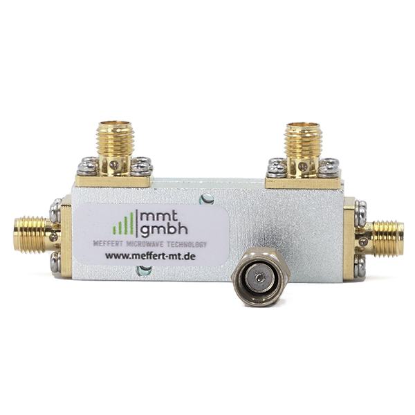
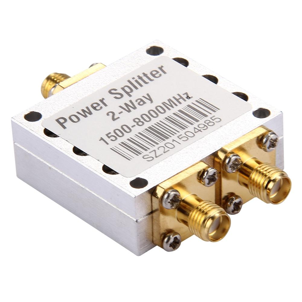
Single Power Divider
21752
Also known as directional coupler or power splitter
21752
21753


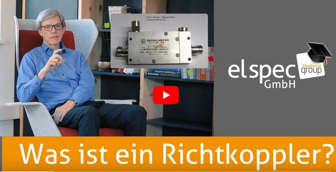
Directional couplers are electrically passive components in the field of high-frequency technology which serve to branch off an electromagnetic power described as a guided wave or to couple it out or into a conductor structure. In an ideal directional coupler, this coupling is strictly selective according to the direction in which the wave passes through the coupler. The technical design depends strongly on the frequency range: for frequencies up to a few MHz, concentrated electronic components such as transformers and capacitors in the form of a bridge circuit are used; from a few 100 MHz upwards to a few 10 GHz, so-called line couplers, for example on electrical circuit boards, in the form of strip lines are used.
A power splitter, also known as directional coupler is specified by several features.
Bandwidth: The bandwidth of the coupler indicates the frequency range (in Hertz) for which the coupler is designed within its specifications.
Rated input power: Couplers have a maximum input power (specified in watts) for both continuous wave and pulsed input signals. This is the maximum power levels for which the component is suitable without degrading its performance or damaging it.
Insertion Loss: This describes the power loss (expressed in decibels (dB)) due to the integration of the component into the main transmission path.
Frequency flatness: Frequency flatness indicates the variation of the amplitude response of the main transmission path (in dB) over the specified bandwidth of the component as a function of the frequency variation of the input signal.
Coupling Coefficient or Coupling Factor: The coupling coefficient is the ratio of the input power to the power at the coupling port (in dB) when the coupler is properly terminated at all ports. This is one of the primary characteristics of the directional coupler. The output signal at the coupling port is proportional to the power level in the direct path from input to output by this known factor. The coupled output can be connected to other instrumentation, such as an oscilloscope, without risk of overloading the instrument.
Isolation: The ratio of the power (in dB) at the input port to the power at the isolated port, with all ports properly terminated.
Directivity: The ratio of the power (in dB) at the coupling port to the power at the isolated port, with all ports properly terminated. For a three port coupler, two power measurements are made: one in the normal forward direction and one with the input and output ports reversed. This specification is a measure of the separation of the forward and reflected components. In general, the higher the directivity, the better the performance of the coupler. Directivity cannot be measured directly. Instead, it is calculated based on the isolation measurement and the reverse isolation measurement.
VSWR: The measured standing wave ratio with all ports of the coupler properly terminated. This value is a measure of the impedance matching of the coupler.
Lauterbachstraße 23c |
82538 Geretsried-Gelting |
elspecgroup.de |
Tel: +49 8171 4357-0 |
Fax: +49 8171 4357-99 |